HROUS
How to choose ultrasonic thickness testing for Australian owners
Choose an ultrasonic thickness testing service by requiring relocatable measurement points, damage-led coverage, documented surface and instrument conditions, verified minima and traceable reporting—not a promised number of readings. These make later wall-loss comparisons defensible. [4][6]

- Core quote requirements: defined survey boundaries and datums, measurement method, calibration checks, location-linked results and recorded limitations. [4]
- Conditional requirements: closer grids around suspected localised damage, coating removal, specialist access or another examination method where conditions warrant them. [4]
1. Define the decision and repeatable locations
Before selecting coverage, define the decision the survey must support—such as repair planning or remaining-life assessment—and identify the asset, component boundaries, material where known, nominal thickness, service conditions, previous results and suspected deterioration mechanism. These details shape the coverage and accuracy needed. [4]
Require a permanent reference system tied to identifiable features, rather than a description of the general area. Welds, nozzles, structural features, chainage and measured offsets can provide references another inspector can relocate. [4]
- Shells and plates: define horizontal and vertical axes, orientation and grid spacing, with locations referenced to identifiable features. [4]
- Pipework: record line and component identifiers, clock position and distance from a defined weld, flange, support or other datum. [4]
Put this in the quote request:
Provide a marked drawing or sketch showing survey boundaries, permanent datums, coordinate and orientation conventions, grid spacing and unique measurement-location identifiers. Define each location sufficiently for a different inspector to relocate it at the next survey. [4]
Keep nominal thickness, the documented measured baseline and the governing minimum thickness distinct. Nominal wall is a reference value, not evidence of what was previously measured at that location. Historical loss comparisons need documented readings from the same location; assessment also needs the applicable minimum. [4][6]
2. Specify damage-led coverage and access exclusions
A broad grid may suit general thinning, but suspected pitting, corrosion under insulation or erosion at elbows and other flow disturbances calls for closer, targeted coverage—not more readings spread across the asset. Ask the proposal to identify relevant dead legs, low points, supports, clamps, injection points and dissimilar-metal interfaces, and explain how each will be covered. [4]
Specify what happens when a low reading appears. Have the inspector lift and replace the probe, repeat the measurement and investigate unstable or unexpected results before accepting them. [4][6] Once validated, tighten the grid around the indication until the extent and shape of the loss are understood. [4] A scan-mode minimum should be confirmed with the probe stationary at an identifiable location; the lowest transient display value is not enough. [6]
Identify access arrangements before work starts, including scaffolding, confined-space controls or permits needed. [4][5] Require inaccessible and uninspected areas to be marked on a sketch, drawing or photographic map; adjacent readings should not stand in for measurements of excluded areas. [4]
The quote should explain the basis for grid spacing, how coverage will expand around confirmed loss and which areas remain excluded without further access. [4]
3. Agree surface preparation and instrument controls
Rough corrosion, scale, thick coatings, poor coupling and internal pitting can impair thickness readings, so agree surface preparation before work starts. Some conditions may require local coating removal, repeat measurements or another examination method. [4]
Require the procedure to state whether coatings will remain, be removed locally or be addressed by the selected measurement mode. [4][6] Echo-to-echo modes may exclude paint but can be unreliable on heavily corroded, thin or highly attenuative material; “through-coating” is not a universal capability. [6]
- Surface conditions: agree the preparation method and record coating treatment, couplant and surface temperature. [4][6]
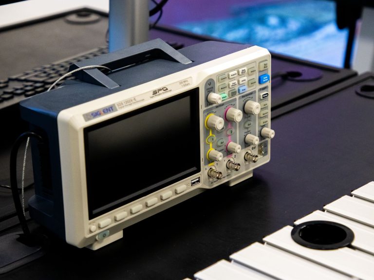
- Instrument configuration: identify the gauge or mapping system, transducer type and frequency, material sound-velocity setting and operator. [4]
- Calibration and verification: specify suitable reference blocks or known-thickness standards, record calibration values, and agree checks before work and at defined points during the survey. [4]
The gauge converts sound travel time into thickness using a material-velocity setting; material properties and temperature can change the appropriate setting. [6] Record settings and temperature conditions so the next inspector can reproduce the method or explain a difference. [4][6] Probe selection must suit the application and surface temperature, because heat can damage a probe and alter sound velocity. [6]
Ask the supplier to propose a procedure, project-specific repeatability criteria and verification schedule for approval. AECTL’s and CIMETRIX’s guidance does not establish a single numerical tolerance or calibration-check interval for every asset. [4][6]
4. Separate deterioration from improved detection
A lower minimum at the next survey does not, by itself, show faster deterioration: a denser grid may find wall loss earlier measurements missed. Historical comparisons need matched locations, comparable methods and a known elapsed interval. [4]
To make that distinction visible, request two labelled groups of results:
- Repeat-location measurements: readings matched to previous coordinates and identifiers, with earlier results, inspection dates and method differences identified. [4]
- Additional investigation points: readings from new locations or tighter grids, kept distinct from the matched historical series. [4]
If an original point is unchanged but closer measurements reveal a nearby pit, the original point supports a local thickness trend; the newly found pit improves knowledge of surrounding damage. Its discovery alone does not establish when the loss occurred or whether deterioration accelerated. [4]
Request a change log covering relocated points, grid density, surface preparation, coating treatment, instrument configuration and inspection limitations. Where comparability has not been established, ask for the reason rather than an unsupported corrosion rate. [4][6]
5. Check the provider’s proposed technique
Ask providers how their proposed technique will deliver relocatable measurements—not simply whether they offer ultrasonic testing. [4] These published capabilities illustrate checks to make, rather than equivalent service packages:
- Access and technique: Victoria-based LMATS advertises Australian drone-mounted UTT with corrosion mapping, live A-scan validation and testing on surfaces up to 260°C. These are vendor-reported capabilities. [1] Ask whether the proposed approach can meet your measurement-location and surface-preparation requirements. [4]
- Complementary methods: D R May Inspections, with a contact location in Corio, Victoria, lists ultrasonic and radiographic thickness measurement and corrosion trending. [2] Ask which method is proposed for each task; its weld-evaluation work is a different application from remaining-wall measurement. [2]
- Reporting and engineering: Gold Coast-based Q-RIIMS advertises Australia-wide UTT, traceable reporting and RPEQ engineering services. Treat its “ISO-accredited and RPEQ-qualified” personnel statements as vendor claims to verify for the assigned team. Ask whether engineering assessment is included or separately commissioned. [3]
Request the assigned personnel’s certification scheme, level, number and expiry, plus the proposed procedure and a sample deliverable linking readings to relocatable coordinates. [4][5] Check that the sample identifies method, equipment, calibration status and limitations—not merely thickness values. [4]
6. Request an itemised quote and variation terms
Turn the inspection scope into quote headings rather than accepting a price attached only to a reading count. Ask suppliers to itemise:
- Defined coverage, grid and measurement method. [4]
- Access arrangements, surface preparation and coating treatment. [4]
- Anomaly verification and additional mapping. [4]
- Exclusions, uninspected areas and report deliverables. [4]
Ask how extra mapping, changed access, preparation or follow-up examinations will be authorised and charged. Request the pricing basis, minimum charges, travel costs, report turnaround, cancellation terms and variation approval process in writing.
Confirm each supplier’s pricing basis, agreed coverage and exclusions in writing before comparing quoted totals.
7. Require a repeat-survey handover
Another inspector should be able to relocate the measurements and identify how they were collected. Include these deliverables in the scope: [4][6]
- Report: asset identification, inspection date and inspector, extent, method, equipment, calibration status, grid definition, readings, confirmed minimum-thickness locations, limitations and photographs. [4][6]
- Location-linked data: marked map, point identifiers, coordinates and underlying readings—not only a colour contour plot. Retain localised minima rather than averaging them away. [4]
- Conditions and configuration: preparation and coating notes, temperature, gauge and probe details, material/sound-velocity setting, calibration reference and unusual-echo notes. [6]
- Exceptions and changes: inaccessible or unreliable points, plus changes in coverage, locations or method against the previous survey. [4][6]
8. Hand the evidence to the responsible engineer
A completed thickness report is evidence, not a safety verdict. Assessment needs the required minimum thickness, design assumptions, corrosion allowance, loading, deterioration and consequences of failure. [4] Leave acceptance limits, remaining-life conclusions and inspection intervals to assessment against the asset’s governing requirements—not a template calculation alone. [4][5]
Standalone thickness gauging is one part of a broader pressure-vessel inspection, which also includes visual examination and safety-device and fittings checks. [5] Keep weld-flaw detection separate from the commissioned remaining-wall measurement scope; D R May lists thickness measurement and weld evaluation as distinct ultrasonic applications. [2]
Ask the responsible engineer to resolve uncertain comparisons, assess confirmed localised loss and determine whether further examination or assessment is needed. Outcomes may include monitoring, expanded inspection, repair or replacement. [4]
References
- RPA – Ultrasonic Thickness Testing – LMATS (lmats.au)
- D R MAY INSPECTIONS | Non-destructive Testing Services | Specialised Testing Services | Inspection Services (drmay.com.au)
- Ultrasonic thickness testing | Gold Coast (qriims.com.au)
- How to Conduct Corrosion Mapping in the Field – AECTL (aectl.com.au)
- Free Ultrasonic Thickness Testing Report (PDF) (maptrack.com, 2026)
- How to Read Thickness Gauge Results Correctly – CIMETRIX Ltd (leebhardnesstesters.com)